How to read the characteristic curves?
How to read the characteristic curve
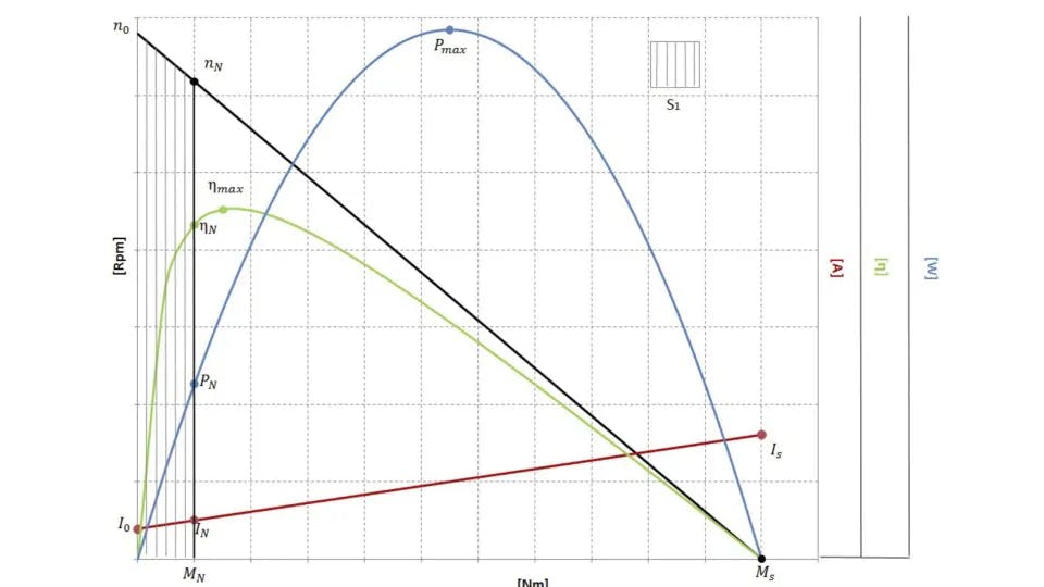
In the first Cartesian dial are shown the Torque, in [Nm] (X axis), the rotation speed, in [Rpm] (Y1 axis), the current consumption in [A] (Y2 axis), the efficiency (Y3 axis).
For completeness, only in this graph, is represented also the output power curve in[W] (Y4 axis). In the technical data sheets the output power curve is not present.
Continuous functioning area
S1
Nominal tension
Vn [V]
Supply tension
No load speed
n0 [Rpm]
Motor's speed with no load applied
No load current
I0 [A]
Current absorbed by the motor with no load applied
Nominal speed
ηN [Rpm]
Minimum speed to which the motor can run continuously
Nominal torque
MN [Nm ]
Maximum torque to which the motor can run continuously
Nominal current
In [A]
Maximum current to which the motor can run continuously
Stall torque
Ms [Nm]
Torque with blocked rotor
Stall current
Is [A]
Current with blocked rotor
Maximum power
Pmax [W]
The maximum power the motor can supply
Maximum efficiency
ηmax
Maximum value of the relation between produced power and supplied power (C*ω)/ (V*I) that is [Nm*rad *s^(-1)]/ [V*A].
To each Torque value corresponds a value of current and speed. Every point, corresponding to a specific load is located on an ideal, vertical line starting from the torque value on the “x” axis.
In the chart is then defined an area called “continuous working area” which encloses all the working condition up to the line defining the nominal values.
The nominal working load is the last one, in ascending order of applied load, to which the motor can work continuously without being damaged. The nominal values written in the technical data sheets are indicative values and to homologate a product it’s necessary to run a life test.
About the life of a Dc motor or a DC gear motor, there are no parameter to define with precision how long can run a motor under a specific load and with a certain duty cycle. Every application has in fact their peculiarities, like mechanical friction, peaking, special environmental conditions, which can condition also strongly the brushes life.
Characteristic curves tolerances
Unless otherwise specified, it must be considered as tolerance for the speed, the area between two lines, parallel to the speed line, drawn from the values of +/- 10% of the no load speed.
For the current, it must be considered a tolerance of +/- 10% of each current value.
These tolerances are applied when the motor is “cold" (20°C).
Discover our motors
Select the engine of your choice to experience the advanced features of our innovative configurator. Once you have chosen the engine, you can use this tool to precisely and comprehensively generate the characteristic curve, providing you with a clear and in-depth visualization of the engine's performance and capabilities under various operating conditions
Direct Current Electric Motors
Ride crafts DC motors and gearmotors for every industry, ensuring tailored performance and reliability.
